
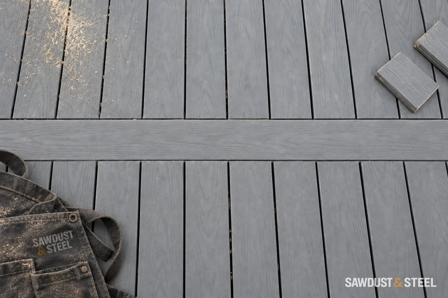
Two short boards meet in the middle of a long deck. It looks like a tiny carpentry decision. Underneath, it can be the place where several details try to occupy the same narrow joist.
A butt joint is where two board ends meet along the same run. A breaker board crosses those runs, so their ends meet its sides instead. Both can work. The choice changes where the seams appear and what must support and fasten each edge.
| Decision | Butt joints | Breaker board |
|---|---|---|
| Appearance | Keeps the main board direction continuous; the end seams remain visible | Creates a deliberate cross-deck line, in the same or a contrasting colour |
| Support | Each meeting board end needs the approved support and fastener arrangement | The cross-board and the ends approaching both sides need support |
| Board order | Plan board lengths and seam positions together | Plan the shorter runs, cross-board and extra framing together |
| Future repair | Check how the selected clips or screws allow an individual board to be released | Check access beside the cross-board before closing the frame |
Trex's current joist-layout example describes a dedicated Trex Hideaway Butt Joint Clip for its compatible shared-joist detail and shows separate support for a breaker-board layout. That does not make an ordinary clip interchangeable with the butt-joint clip. Match the board, fastener and current installation detail; neither a doubled joist nor a single shared joist is a universal answer for every system.
Support and spacing are separate checks. Keep the required composite-board expansion gaps at the selected joint, even when a tighter seam would look tidier on installation day.
Draw what happens below the seam
Trex publishes fastening and installation instructions for its current systems. Use the detail for the exact boards and clips. Do not assume one shared clip or a familiar double-joist detail is suitable for every product.
A visible line can be intentional
A breaker board can align with stairs, a door, or a change in seating area. Ask for a plan showing its framing as well as its colour. Consider offcuts and replacement access too: saving a board on the order is less impressive if the layout creates an awkward repair later.
Draw every board, including the last narrow strip
Choose the board lengths and direction before the framing layout is frozen. Draw the actual board width plus its specified gap across the full deck. This reveals whether the last board against the house becomes an awkward narrow strip and whether a border steals usable width at the stair. Centre a pattern only after checking the outer edges; a neat middle does not rescue an unsupported sliver beside the wall.
| Layout | Support to show | Finish detail to settle |
|---|---|---|
| Butt joint | Both board ends and the approved clip or face-fastener arrangement. | Temperature-dependent end gap. |
| Breaker board | Support beneath the transverse board and each terminating field-board end. | Gaps on both sides and fastening access. |
| Picture-frame border | Perimeter blocking supporting the border and the field-board ends. | Outside edge, corner joint and fascia relationship. |
| Straight ends | Permitted overhang beyond the last support. | Visible cut ends and fascia height. |
Look under the seam on the drawing
Butt joint: two ends along one run
The board ends meet end-to-end. Both ends need the specified bearing and fastener arrangement; the required movement gap is a separate detail.
Breaker board: support three interfaces
A transverse board separates the field runs. Support must carry that board and the field-board ends on both sides. Drawing the top pattern alone misses those interfaces.
Boards are shown transparent so you can see the support zones. Follow the exact board, clip and framing instructions: Trex's dedicated butt-joint clip detail does not apply to ordinary clips. Trex joist and butt-joint details.
Approve a complete corner, not just the board colour
Ask for one corner showing the board profile, permitted overhang, fasteners, border joint, fascia and ventilation space. A mitred border can expose movement as its two pieces change length. A square joint looks different and still needs its prescribed gaps and support. Neither is automatically better; compare the finished detail at the scale you will actually see from the door.
Use a small dry mock-up if the edge treatment is hard to picture. Include the fascia thickness so the border does not unexpectedly project too little or too much. If the fascia later waves, investigate its own movement and fastener detail rather than treating it as a continuation of the walking boards. Keep access to fasteners in mind: a beautiful border that makes one damaged field board very difficult to replace has a maintenance cost.
Before the next step
- Mark every end joint on the board plan.
- Confirm the support and approved fastening at each edge.
- Compare complete framing and board quantities for both layouts.
Put both layouts on the same framing drawing before choosing. You want to see where the joints land and what supports them, not discover the extra work halfway through laying boards. Check the barbecue operating space before fixing the deck layout.